![]()
![]()
![]()
![]()
![]()
![]()
![]()
![]()
![]()
![]()
Copyright © 2008-2012 CPUStick.com;
all rights reserved.
Patent U.S. 8,117,587.

Examples:
- Toaster Oven Temperature Profile Controller
- LCD Digital Thermometer
- ZigFlea™ Wireless Remote LED Dimmer
- FSLBOT Walking Robot
- Get Intimate (and Interactive!) With Your MCU!
Toaster Oven Temperature Profile Controller
A simple embedded system, like a toaster oven temperature profile controller, can be brought online in record time!
It’s as easy as...
- wire the MCU I/O pins to the embedded circuit
- wire MCU pin an0 to thermocouple op-amp output (I use an LM358)
- wire MCU pin an1 to solid state relay control input (I use a Teledyne STH24D25)
- install the cpustick.inf file by saving it to a file, right-clicking on the file, and selecting "Install"; you can ignore warnings about an unsigned driver package -- the driver is straight from Microsoft, and only the INF file is unsigned; the INF file allows Windows to bind a human readable name, "CPUStick", to the USB VID/PID presented to the host by StickOS
- connect a host computer to the USB interface on the MCU
- let the host computer automatically install the new hardware
- open a Hyper Terminal console window and connect to the MCU; press <Enter> for a command prompt
- configure the MCU I/O pins as appropriate
- configure pin an0 as an analog input
- configure pin an1 as a digital output
- write and debug your BASIC control program, live on the MCU (see below)
- type “save”
- type “autorun on”
- turn the toaster oven full on (so that the relay can control it)
- type “reset”
- disconnect the host computer from the USB interface on the MCU
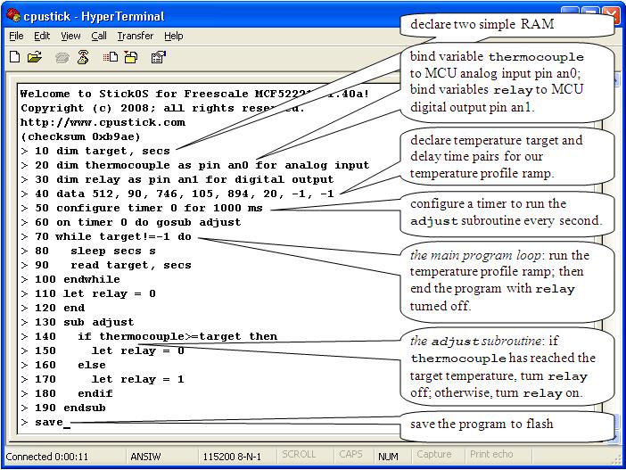
The entire toaster oven temperature profile controller BASIC control program is shown below:
(see the examples in text format)
- Line 10 declares two simple RAM variables named “target” and “secs” for use in the program, and initializes them to 0.
- Line 20 declares an analog input "pin variable" named “thermocouple” that is bound to pin an0, to read the thermocouple voltage, in millivolts
- Line 30 declares a digital output "pin variable" named “relay” that is bound to pin an1, to control the solid state relay.
- Line 40 declares the temperature target and delay time pairs for our temperature profile ramp.
- Lines 50 and 60 configure a timer interrupt to call the "adjust" subroutine asynchronously, every second, while the program runs.
- Lines 70 thru 100 set the target temperature profile while the program runs.
- Lines 110 and 120 end the program with the solid state relay control turned off.
- Lines 130 thru 190 use the declared pin variables to simply turn the solid state relay control off if the target temperature has been achieved, or on otherwise.
Then:
- “save” saves the program to non-volatile flash memory.
- “autorun on” sets the program to run automatically when the MCU is powered up.
- Finally, “reset” resets the MCU as if it was just powered up.
Note that if terse code were our goal, lines 60 and 130 thru 190 could have all been replaced with the single statement:
> 60 on timer 0 do let relay = thermocouple<target
LCD Digital Thermometer
With the advent of advanced serial peripherals based on the I2C or QSPI serial interfaces, embedded systems can take on a whole new level of real-world functionality!
An LCD digital thermometer, displaying both Celsius and Fahrenheit, can be brought online in minutes, with just a quick study of the I2C peripheral register or protocol definitions! The peripherals are:
- Texas Instruments TMP102 temperature sensor, at I2C address 0x48
-
NewHaven Display NHD-C0220BiZ-FS(RGB)-FBW-3VM LCD display based on
the ST7036 controller, at I2C address 0x3c
It’s as easy as...
- wire MCU to its embedded circuit
- wire MCU pin scl to the temperature sensor, LCD display, and pull-up resistor
- wire MCU pin sda to the temperature sensor, LCD display, and pull-up resistor
- note that the COG ST7036 cannot sink more than about 10k ohm of pull-up!
- connect a host computer to the USB interface on the MCU (see above)
- write and debug your BASIC control program, live on the MCU (see below)
- type “save”
- type “autorun on”
- type “run”
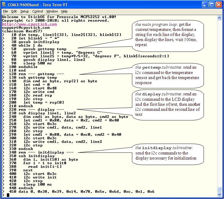
The entire LCD digital thermometer BASIC control program is shown below:
(see the examples in text format)
- Line 10 declares four RAM variables: an integer to hold the current temperature in degrees C, two strings to represent the two lines of the display, and a third string used to blink an "activity indicator" on the display every two seconds.
- Line 20 initializes the activity indicator string to contain a space and an asterisk; these characters will be alternated on the right hand side of the second display line every other second.
- Line 30 initializes the LCD display by calling the "initdisplay" subroutine.
- Lines 40-100 are the
main program loop:
- first, we get the current temperature by calling the "gettemp" subroutine,
- then, we format a string for the first line of the display in degrees Celsius,
- then, we format a string for the second line of the display in degrees Fahrenheit, and include the activity indicator, and
- finally, we display both lines by calling the "display" subroutine.
- Lines 130-210 are the "gettemp" subroutine, which use the I2C protocol on the temperature sensor to extract degrees Celsius
- Lines 230-330 are the "display" subroutine, which use the I2C protocol on the LCD display to display two lines of text
- Lines 350-440 are the "initdisplay" subroutine, which use the I2C protocol to initialize the LCD display
- Line 450 is read-only data used by the "initdisplay" subroutine to initialize the LCD display.
Then:
- “save” saves the program to non-volatile flash memory.
- “autorun on” sets the program to run automatically when the MCU is powered up.
- Finally, “run” runs the program.
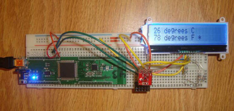
Here is the LCD digital thermometer in action:
ZigFlea™ Wireless Remote LED Dimmer
With the aid of an MC13201 ZigFlea™ Wireless Transceiver, a simple wireless embedded system, like a remote LED dimmer, can be brought online just as easily as a local embedded system!
It’s as easy as...
- set the 2.4GHz zigflea wireless nodeid on each MCU
- wire MCU #1 to its embedded circuit
- wire MCU #1 pin an0 to the potentiometer
- wire MCU #2 to its embedded circuit
- wire MCU #2 pin dtin0 to the LED
- connect a host computer to the USB interface on MCU #1
- write and debug your BASIC control program, live on MCU #1 (see below)
- use the 2.4GHz zigflea wireless transport to connect to MCU #2
- write and debug your BASIC control program, live on MCU #2 (see below)
- run the program on MCU #2
- disconnect from MCU #2
- run the program on MCU #1
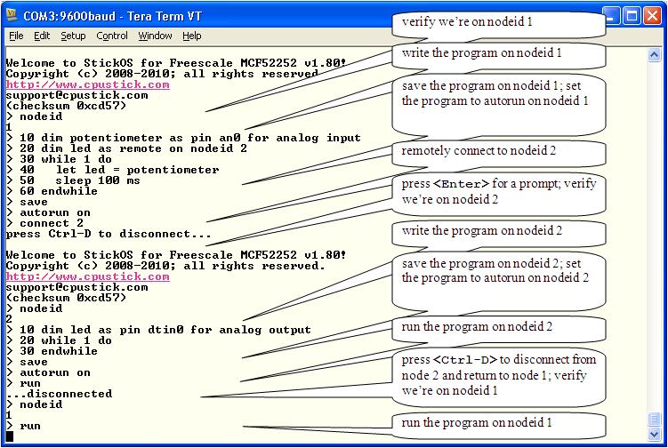
The entire debugging session, including the writing and running of both MCU’s BASIC control programs, is shown below:
(see the examples in text format)
Note that all of this debugging session is occurring on the Hyper Terminal connected to the USB interface on MCU #1!
First we write the program on MCU #1.
- Notice in line 10 that we declare a local pin variable named “potentiometer” to read the value of the potentiometer, through analog input pin an0, in millivolts.
- Then, in line 20, we declare a remote pin variable to control the LED on MCU #2 (through MCU #2’s local pin variable!); the “as remote on nodeid 2” indicates that the real variable declaration is found on MCU #2.
- Then we simply enter an infinite loop reading the value of the potentiometer (again, in millivolts) every 100ms, and writing it to the LED on MCU #2.
We then save the program to flash memory on MCU #1 and configure it to run automatically when the MCU powers up.
Then we remotely connect to MCU #2 and write its program.
- Notice in line 10 that we declare a local pin variable named “led” to control the LED, through analog output pin dtin0, in millivolts.
- Then we simply enter an infinite loop, waiting for our local pin variable to be written remotely from MCU #1 every 100ms!
We then save the program to flash memory on MCU #2 and configure it to run automatically when the MCU powers up.
Finally, we run the program on MCU #2, disconnect from MCU #2 by pressing <Ctrl-D>, and run the program on MCU #1.
At this point, adjusting the potentiometer on MCU #1 causes the LED brightness on MCU #2 to be correspondingly adjusted, after a 100ms delay!!!
FSLBOT Walking Robot
Running inside the TWR-MECH board of the FSLBOT, this program allows the robot to walk or stop or blink its mouth lights when the facial sensors are touched; the potentiometer controls the walking speed.
See a short video:

Use "auto" to load the program below and run with the potentiometer at mid-range.
N.B. this program uses v1.90 features.
// *** fslbot demo ***
// touch mouth to blink leds
// adjust potentiometer for walk speed
// touch left/right cheek to take 6 steps leading from left/right
// touch forehead to stop march
//
dim mpr121
mpr121 = 0x5a  // i2c address
dim ioex
ioex = 0x38  // i2c address
//
dim blink, lit  // state of the mouth LEDs
dim right, left  // counts of steps to take
//
// *** initialize our modules ***
gosub mpr121_init
gosub mouth_init
//
// *** configure the mpr121_isr ***
dim isr as pin irq7* for digital input inverted
on isr do gosub mpr121_isr
//
// *** configure the mouth_timer ***
configure timer 1 for 300 ms
on timer 1 do gosub mouth_timer
//
// *** configure the servo pins ***
dim rfoot as pin dtin0 for servo output
dim rhip as pin dtin1 for servo output
dim lhip as pin dtin2 for servo output
dim lfoot as pin dtin3 for servo output
//
// *** configure the walk speed potentiometer
dim pot as pin an6 for analog input
//
// *** set the walk stride variables ***
dim delay
dim flower, fstart, fraise, ftip, hshift
delay = 15
flower = 600, fstart = 150, fraise = 230, ftip = 50, hshift = 250
//
// *** stand square ***
gosub stand
//
// *** main loop -- just walk ***
//
while 1 do
  if left>right&&left>0 then
    // lead with the left foot
    gosub left_step
    left = left-2
  elseif right>left&&right>0 then
    // lead with the right foot
    gosub right_step
    right = right-2
  else
    gosub stand
  endif
  delay = pot*15/1650
endwhile
end
//
// *** walking subroutines ***
//
sub right_step
  // step the right foot
  lfoot = 0  // relax left foot
  for rfoot = rfoot to 1500+flower step 10  // lean left
    sleep delay ms
  next
  for lfoot = 1500+fstart to 1500+fraise step 10  // stand left
    sleep delay ms
  next
  do   // take right step
    if rfoot>1500+ftip then
      rfoot = rfoot-10
    endif
    if rhip>1500-hshift then
      rhip = rhip-10
      lhip = rhip
    endif
    sleep delay ms
  until rfoot<=1500+fstart&&rhip<=1500-hshift
  for lfoot = lfoot to 1500 step -10  // fall back right
    sleep delay ms
  next
endsub
//
sub left_step
  // step the left foot
  rfoot = 0  // relax right foot
  for lfoot = lfoot to 1500-flower step -10  // lean right
    sleep delay ms
  next
  for rfoot = 1500-fstart to 1500-fraise step -10  // stand right
    sleep delay ms
  next
  do   // take left step
    if lfoot<1500-ftip then
      lfoot = lfoot+10
    endif
    if lhip<1500+hshift then
      lhip = lhip+10
      rhip = lhip
    endif
    sleep delay ms
  until lfoot>=1500-fstart&&lhip>=1500+hshift
  for rfoot = rfoot to 1500 step 10  // fall back left
    sleep delay ms
  next
endsub
//
sub stand
  // stand square
  rfoot = 1500, rhip = 1500, lhip = 1500, lfoot = 1500
endsub
//
// *** mouth subroutines ***
//
sub mouth_timer
  dim r as byte, d as byte
  // blink all bits if we're supposed to
  if blink then
    lit = ~lit
    r = 1, d = lit
    i2c start ioex
    i2c write r, d
    i2c stop
  endif
endsub
//
sub mouth_init
  dim r as byte, d as byte
  // configure bits for output
  r = 3, d = 0
  i2c start ioex
  i2c write r, d
  i2c stop
endsub
//
// *** touch subroutines ***
//
sub mpr121_isr
  dim bits
  // get the touch value and respond appropriately
  gosub mpr121_poll bits
  if bits&128 then
    // print "mouth"
    blink = !blink
  endif
  if bits&64 then
    // print "forehead"
    left = 0, right = 0
  endif
  if bits&32 then
    // print "left cheek"
    left = 6, right = 5
  endif
  if bits&16 then
    // print "right cheek"
    right = 6, left = 5
  endif
endsub
//
sub mpr121_poll bits
  dim r as byte, r0 as byte, r1 as byte
  // read and return both bytes of the touch register
  i2c start mpr121
  r = 0
  i2c write r
  i2c read r0
  r = 1
  i2c write r
  i2c read r1
  i2c stop
  bits = r1<<8|r0
endsub
//
sub mpr121_init
  dim i
  dim r as byte, d as byte
  // just follow AN3944: MPR121 Quick Start Guide
  i2c start mpr121
  for i = 1 to 0x17 step 2
    r = 0x40+i, d = 0xf
    i2c write r, d
    r = 0x41+i, d = 0xa
    i2c write r, d
  next
  restore mpr121
  do
    read r, d
    i2c write r, d
  until r==0x5e
  i2c stop
  label mpr121
  data 0x2b, 0x1, 0x2c, 0x1, 0x2d, 0x0, 0x2e, 0x0
  data 0x2f, 0x1, 0x30, 0x1, 0x31, 0xff, 0x32, 0x2
  data 0x5d, 0x4, 0x7b, 0xb, 0x7d, 0x9c, 0x7e, 0x65
  data 0x7f, 0x8c, 0x5e, 0x8c
endsub
Get Intimate (and Interactive!) With Your MCU!
The following advanced examples show how you can use StickOS MCU register variables to talk directly to MCU peripheral registers, either interactively thru the command line or thru a BASIC program!
N.B. these examples use v1.90 features; use "let" keywords below for earlier versions of StickOS.
All you need to know is the register address and register definition and you can interact even with peripherals like the MCF52259 Random Number Generator, that StickOS otherwise knows nothing about:
Welcome to StickOS for Freescale MCF52259 v1.92c!
Copyright (c) 2008-2010; all rights reserved.
https://github.com/rtestardi/StickOS
support@cpustick.com
(checksum 0x1d7)
> rem configure the random number generator (rng) registers
> dim rngcr at address 0x401f0000
> dim rngsr at address 0x401f0004
> dim rngout at address 0x401f000c
>
> rem check if the rng is running?
> print hex rngsr, rngout
0x10000 0x0
>
> rem turn on the rng
> rngcr = 0x01
>
> rem now check the rng again!
> print hex rngsr, rngout
0x1010e 0xf3e56c84
> print hex rngsr, rngout
0x10108 0xfe7ac1db
> print hex rngsr, rngout
0x10108 0x8b0f444e
> _
As another example, you can even program ISR's by configuring the MCF52259 Programmable Interrupt Timer 1 (PIT1), that StickOS otherwise does not use, by hand, like:
> list
10 dim ppmrh at address 0x4000000c
20 dim pcsr1 as short at address 0x40160000
30 dim pmr1 as short at address 0x40160002
40 ppmrh = ppmrh&~0x10 // enable pit1 clocks
50 pmr1 = 1220 // configure pit1 for 1 Hz
60 pcsr1 = 0xf7b // 32k prescale, reload, pit enable
70 on pcsr1&0x4 do gosub isr // pit1 interrupt flag
80 halt
100 sub isr
110 pcsr1 = pcsr1|0x4 // clear the interrupt flag
120 print "isr at", seconds, "seconds"
130 endsub
end
> run
isr at 974 seconds
isr at 975 seconds
isr at 976 seconds
isr at 977 seconds
isr at 978 seconds
<Ctrl-C>
STOP at line 80!
> _
This makes for a trivial and interactive (and maybe even fun!) way to learn and discover peripheral operation of the MCU! Of course, you can do the same to learn and discover external i2c and spi peripherals as well -- interactive rocks! :-)
[Note that you can trivially crash your
MCU by accessing registers incorrectly, so be sure to set up your safemode
pin attached to the “autorun disable” switch before you autorun any program
that uses MCU register variables, and save your changes often!]