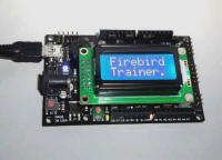
 The
Firebird32 is a low cost development board that can be used with StickOS BASIC
or the C Flexisframework™.
 The
Firebird32 is a low cost development board that can be used with StickOS BASIC
or the C Flexisframework™.
Introduction to StickOS BASIC Programming on the Firebird32
Check your Firebird32 jumpers: Setting the Firebird32 Jumpers
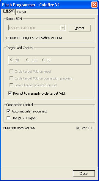
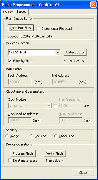
If your Firebird32 did not come with StickOS BASIC preinstalled, see: Loading StickOS BASIC onto your Firebird32 using USBDM
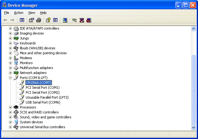
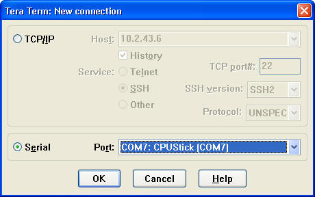
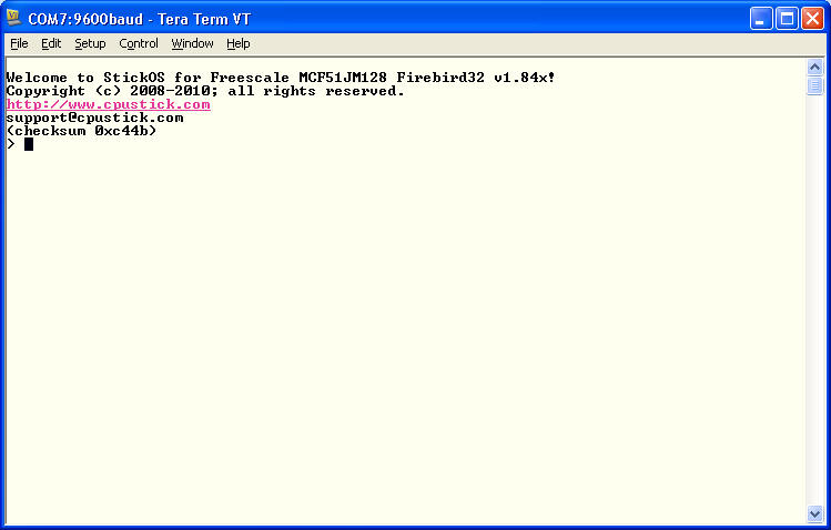
If you have not yet connected to your Firebird32 MCU with Tera Term, see: Connecting to the Firebird32 MCU with Tera Term
Start the Tera Term terminal emulator and connect to your Firebird32.
You can access the StickOS BASIC online help thru the "help" command:
Welcome to StickOS for Freescale MCF51JM128 Firebird32 v1.84b!
Copyright (c) 2008-2010; all rights reserved.
https://github.com/rtestardi/StickOS
support@cpustick.com
(checksum 0x1c3)
> help
for more information:
help about
help commands
help modes
help statements
help blocks
help devices
help expressions
help strings
help variables
help pins
help zigflea
see also:
https://github.com/rtestardi/StickOS
> _
First, let's get acquainted with the Firebird32 pin names:
> help pins
pin names:
a0-a7, 0-13
pta[0-5], ptc[0-1,3-6], ptd[0,3-7], pte7, ptf[5,7], ptg[0-2]
jumpers:
d6=pwm
all pins support general purpose digital input/output
a?, 7 = potential analog input pins (mV)
3,5,6,8,9,10,11 = potential analog output (PWM) pins (mV)
3,5,6,8,9,10,11 = potential servo output (PWM) pins (us)
3,5,6,8,9,10,11 = potential frequency output pins (Hz)
> _
This shows that the basic arduino-shield pin names are as follows:
shield analog pins a0 - a7 a0 - a7 shield digital pins 0 - 13 0 - 13
Pins a0 - a7 can be used for analog input into the MCU. Pins 0 - 13 can be used for digital input or output into or out of the MCU. In addition, digital pins 3, 5, 6, 8, 9, 10, and 11 can be used for analog output, servo output, or frequency output out of the MCU.
In StickOS BASIC, MCU pins are bound to ordinary program variables and then can be examined or manipulated, both in a BASIC program as well as interactively from the command line, using any BASIC statements that can access variables, such as "print" or "let".
These "pin variables" are declared with the following statement:
dim varpin as pin pinname for (digital|analog|servo|frequency|uart) (input|output) \
[debounced] [inverted] [open_drain]
This means you can examine analog input pin a0, in millivolts, like:
> dim pot as pin a0 for analog input
> print pot
4125
> _
You can examine digital input pin 1 like:
> dim switch as pin 1 for digital input
> print switch
1
> _
You can manipulate digital output pin 2 like:
> dim led as pin 2 for digital output
> let led=0
> _
And for pins 3, 5, 6, 8, 9, 10, and 11 you can also use the PWM functions of analog output (millivolts), servo output (microseconds), or frequency output (Hz), like:
> dim motor as pin 3 for servo output
> let motor=1000
> _
Replace the keyword "servo" with "analog" or "frequency" for the other output pin types.
To clear variable and pin definitions (so they can be redefined), do:
> clear
> _
From the Firebird32 schematic, in addition to the arduino-shield pins of a0-a7, 0-13, there are a few other pins connected to the internal components on the board.
These pins are as follows:
switch ptg0 buzzer ptf5 rgb anode (+) ptg1 rgb red cathode (-) 5 (pte3) rgb green cathode (-) 3 (pte2) rgb blue cathode (-) 9 (ptf1) eeprom write protect ptg2 scl ptc0 sda ptc1 txd2 ptc3 rxd2 ptc5 tx can ptf7 rx can ptc6 spi chip select pte7 spi chip select ptc4
Now let's make the buzzer on the board sound 440 Hz:
> dim buzzer as pin ptf5 for frequency output
> let buzzer=440
> _
The first line configures the MCU pin connected to the buzzer (ptf5) for frequency output, and the second line sets it generating a 440Hz tone.
And now let's turn it off again:
> let buzzer=0
> _
Pretty darn easy!
Now let's make the green LED (of the rgb LED on the board)) blink. This is a bit tougher since we have to configure the anode of the LED to +V as well as blink the cathode of the LED. We can write a trivial BASIC program to do this:
> new
> 10 dim anode as pin ptg1 for digital output
> 20 dim green as pin 3 for digital output
> 40 let anode=1
> 50 while 1 do
> 60 let green=!green
> 70 sleep 500ms
> 80 endwhile
> save
> run
_
The first command, "new", clears any existing BASIC program. The next 8 lines of code are the program itself, which configures the MCU pin connected to the anode of the LED (ptg1) as an output and binds it to the variable "anode", and then configures the MCU pin connected to the green cathode of the LED (arduino-shield pin 3) as an output and binds it to the variable "green". From then on examination or modification of those variables is reflected immediately at the corresponding MCU pin. Then, we set the anode of the LED to a high voltage, and finally we enter a program infinite loop that inverts the state of the green cathode every 500ms!
The command "save" causes the program to be saved to non-volatile flash memory (initially, new program lines and changed program lines are entered into RAM, to preserve flash memory lifetime). The command "run" causes the program to run, and the green LED should be blinking (in addition to the heartbeat LED)!
Press <Ctrl-C> to stop the program:
<Ctrl-C>
STOP at line 70!
> _
The program stopped at line 70.
At this point, you can make the green LED blink yourself! Enter the following lines and watch the green LED:
> let green=!green
> let green=!green
> let green=!green
> _
Once you have entered a line, you can use the up-arrow cursor key to recall previously entered lines. You can use the right-and-left arrow keys to move the cursor and insert or delete (with backspace) characters.
It we want to change the program to blink faster, we need simply edit line 70, using the "edit" command as follows:
> edit 70
> 70 sleep 500 ms_
Note that the cursor is at the end of the line; you can move it left to the last "0" in "500" and backspace to erase it; then press <Enter>:
> 70 sleep 50 ms
> _
Now list the program with the "list" command:
> list
10 dim anode as pin ptg1 for digital output
20 dim green as pin 3 for digital output
40 let anode = 1
50 while 1 do
60 let green = !green
70 sleep 50 ms
80 endwhile
end
> _
And you can continue the changed program running from where it stopped previously with the "cont" command:
> cont
_
Notice the green LED now blinks 10x faster.
Again, press <Ctrl-C> to stop the program:
<Ctrl-C>
STOP at line 70!
> _
As one final tweak, we can make the green LED stop blinking whenever the switch on the board (not the reset switch!) is pressed, with:
> 5 dim switch as pin ptg0 for digital input inverted
> 55 if !switch then
> 65 endif
> list
5 dim switch as pin ptg0 for digital input inverted
10 dim anode as pin ptg1 for digital output
20 dim green as pin 3 for digital output
40 let anode = 1
50 while 1 do
55 if !switch then
60 let green = !green
65 endif
70 sleep 50 ms
80 endwhile
end
> run
_
Line 5 configures the MCU pin connected to the switch (ptg0) as an input and binds it to the variable "switch" with an inverted sense (since the circuit ties the MCU pin to ground when the switch is pressed). Line 55 says that if the switch is not pressed, do line 60 (which makes the green LED blink). Line 65 ends the if condition started at line 55.
Notice the green LED now stops blinking when you press the switch.
Again, press <Ctrl-C> to stop the program:
<Ctrl-C>
STOP at line 70!
> _
Finally, if we insert many lines in the program this way, it makes the program look cleaner to then renumber the lines with the "renumber" command:
> renumber
> list
10 dim switch as pin ptg0 for digital input inverted
20 dim anode as pin ptg1 for digital output
30 dim green as pin 3 for digital output
40 let anode = 1
50 while 1 do
60 if !switch then
70 let green = !green
80 endif
90 sleep 50 ms
100 endwhile
end
> _
Notice that the lines are evenly numbered by 10 again.
For a whirlwind tour of StickOS BASIC, be sure to download the StickOS Quick Reference guide.
Also see the full online StickOS User's Guide, or the StickOS User's Guide in PDF format.
Have fun!
Setting the Firebird32 Jumpers
In general there is no need to ever move jumpers D6 or D10 off the PWM position; you may always refer to these lines as pins "6" or "10".
Set jumper D11 to MOSI to use SPI, and to PWM otherwise; note that to use SPI in StickOS BASIC you must explicitly toggle a chip select line (often pin "10").
Set jumpers A4 and A5 to SDA and SCL to use I2C, and to A4 and A5 otherwise.
Connecting to the Firebird32 MCU with Tera Term
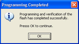
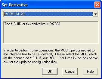
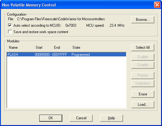
Loading StickOS BASIC onto your Firebird32 using USBDM CFV1_FlashProgrammer
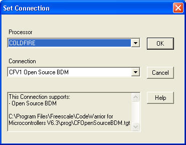
Configuring HiWave.exe to use the USBDM (advanced, optional)
The Firebird32 Demo Program:
This program plays Yankee Doodle on the buzzer three times while cycling the RGB LED thru a sequence of colors. It scans the switch on the board for an indication to silence playback early. It also initialized the LCD display (if attached) and scans the keypad (if attached) and displays pressed keys on the LCD. Finally, it queries the console (USB or UART) for input and if input is found, displays that on the LCD as well.
10 dim n, text$[16]
20 rem --- kdb ---
30 on keychar do lcd n%2, keychar$
40 rem --- buzzer ---
50 dim plays, note, sustain, scale[13]
60 dim notes[40] as byte, octave[40] as byte, duration[40] as byte
70 dim cancel as pin ptg0 for digital input inverted
80 dim buzzer as pin ptf5 for frequency output
90 gosub buzinit
100 configure timer 1 for 250 ms
110 on timer 1 do gosub buznote
120 rem --- rgb ---
130 dim rgb
140 dim red as pin 5 for analog output inverted
150 dim green as pin 3 for analog output inverted
160 dim blue as pin 9 for analog output inverted
170 dim vcc as pin ptg1 for digital output
180 let vcc = 1
190 configure timer 2 for 100 ms
200 on timer 2 do gosub rgbcycle
210 rem --- main loop ---
220 let text$ = "Firebird"
230 lcd 0, text$
240 let text$ = "CFV1"
250 lcd 1, text$
260 while 1 do
270 input text$
280 lcd n%2, text$
290 let n = n+1
300 endwhile
310 end
320 rem --- sub buznote ---
330 sub buznote
340 if cancel||plays>=3 then
350 let buzzer = 0
360 off timer 1
370 return
380 endif
390 if sustain then
400 let sustain = sustain-1
410 return
420 endif
430 if !duration[note] then
440 let note = 0
450 let plays = plays+1
460 endif
470 let buzzer = scale[notes[note]]*octave[note]
480 let sustain = 4/duration[note]-1
490 let note = note+1
500 endsub
510 rem --- sub buzinit ---
520 sub buzinit
530 dim i
540 restore buzdata
550 while 1 do
560 read notes[i], octave[i], duration[i]
570 if !duration[i] then
580 break
590 endif
600 let i = i+1
610 endwhile
620 for i = 0 to 12
630 read scale[i]
640 next
650 read i
660 assert i==-1
670 endsub
680 label buzdata
690 data 10, 1, 4, 10, 1, 4, 12, 1, 4, 2, 2, 4
700 data 10, 1, 4, 2, 2, 4, 12, 1, 4, 5, 1, 4
710 data 10, 1, 4, 10, 1, 4, 12, 1, 4, 2, 2, 4
720 data 10, 1, 2, 9, 1, 2
730 data 10, 1, 4, 10, 1, 4, 12, 1, 4, 2, 2, 4
740 data 3, 2, 4, 2, 2, 4, 12, 1, 4, 10, 1, 4
750 data 9, 1, 4, 5, 1, 4, 7, 1, 4, 9, 1, 4
760 data 10, 1, 2, 10, 1, 2
770 data 0, 0, 1, 0, 0, 1, 0, 0, 1
780 data 0, 0, 0
790 data 440, 466, 494, 523, 554, 587
800 data 622, 659, 698, 740, 784, 831, 880
810 data -1
820 rem --- sub rgbcycle ---
830 sub rgbcycle
840 let rgb = (rgb+analog/10)%(analog*3)
850 if rgb<analog then
860 let green = rgb, red = analog-rgb, blue = 0
870 elseif rgb<analog*2 then
880 let blue = rgb-analog, green = analog*2-rgb, red = 0
890 else
900 let red = rgb-analog*2, blue = analog*3-rgb, green =
0
910 endif
920 endsub
Note that for the Firebird32 Nano or Mini the following lines should be substituted for those above:
140 dim red as pin pte3
for analog output inverted
150 dim green as pin pte2 for analog output inverted
160 dim blue as pin ptf1 for analog output inverted