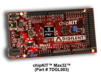
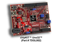
The
chipKIT is a low cost development board that can be used with StickOS BASIC or using the
arduino-compatible MPIDE.

Introduction to StickOS BASIC Programming on the chipKIT
Check your chipKIT jumpers: Setting the chipKIT Jumpers
If you have not yet loaded StickOS BASIC on your chipKIT, see: chipKIT avrdude Bootloader
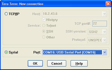
If you have not yet connected to your chipKIT MCU with Tera Term, see: Connecting to the chipKIT MCU with Tera Term
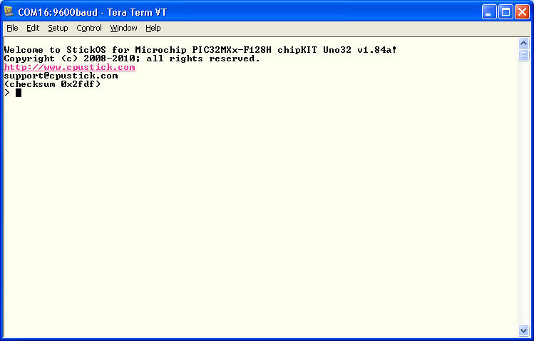
Start the Tera Term terminal emulator and connect to your chipKIT.
You can access the StickOS BASIC online help thru the "help" command:
Welcome to StickOS for Microchip PIC32MXx-F128H chipKIT Uno32 v1.84a!
Copyright (c) 2008-2010; all rights reserved.
https://github.com/rtestardi/StickOS
support@cpustick.com
(checksum 0x2fdf)
> help
for more information:
help about
help commands
help modes
help statements
help blocks
help devices
help expressions
help strings
help variables
help pins
help zigflea
see also:
https://github.com/rtestardi/StickOS
> _
First, let's get acquainted with the chipKIT pin names:
> help pins
pin names:
a0-a11, 0-13, 26-41, 43, rg2, rg3, rg9
jumpers:
jp5,jp6=master, jp4=rd4
all pins support general purpose digital input/output
a? = potential analog input pins (mV)
3,5,6,9,10 = potential analog output (PWM) pins (mV)
3,5,6,9,10 = potential servo output (PWM) pins (us)
3,5,6,9,10 = potential frequency output pins (Hz)
> _
This shows that the basic arduino-shield pin names are as follows:
shield analog pins a0 - a11 a0 - a11 shield digital pins 0 - 13 0 - 13 shield digital pins 26-41 26 - 41
Pins a0 - a11 can be used for analog input into the MCU. Pins 0 - 13, and 26 - 41 can be used for digital input or output into or out of the MCU. In addition, digital pins 3, 5, 6, 9, and 10 can be used for analog output, servo output, or frequency output out of the MCU.
In StickOS BASIC, MCU pins are bound to ordinary program variables and then can be examined or manipulated, both in a BASIC program as well as interactively from the command line, using any BASIC statements that can access variables, such as "print" or "let".
These "pin variables" are declared with the following statement:
dim varpin as pin pinname for (digital|analog|servo|frequency|uart) (input|output) \
[debounced] [inverted] [open_drain]
This means you can examine analog input pin a0 (where you may have a pot attached), in millivolts, like:
> dim pot as pin a0 for analog input
> print pot
4125
> _
You can examine digital input pin 1 (where you may have a switch attached) like:
> dim switch as pin 1 for digital input
> print switch
1
> _
You can manipulate digital output pin 2 (where you may have an LED attached) like:
> dim led as pin 2 for digital output
> let led=0
> _
And for pins 3, 5, 6, 9, and 10 you can also use the PWM functions of analog output (millivolts), servo output (microseconds), or frequency output (Hz), like:
> dim motor as pin 3 for servo output
> let motor=1000
> _
Replace the keyword "servo" with "analog" or "frequency" for the other output pin types.
To clear variable and pin definitions (so they can be redefined), do:
> clear
> _
If we were to connect a buzzer to the board on pin 3, we could make it sound 440 Hz with:
> dim buzzer as pin 3 for frequency output
> let buzzer=440
> _
The first line configures the MCU pin connected to the buzzer (3) for frequency output, and the second line sets it generating a 440Hz tone.
And now let's turn it off again:
> let buzzer=0
> _
Pretty darn easy!
From the chipKIT schematic, in addition to the arduino-shield pins of a0-a11, 0-13, 26-41, there are a few other pins connected to the internal components on the board.
These pins are as follows:
auxiliary led 43
Now let's make the auxiliary LED on the board blink. We can write a trivial BASIC program to do this:
> new
> 10 dim led as pin 43 for digital output
> 20 while 1 do
> 30 let led=!led
> 40 sleep 500ms
> 50 endwhile
> save
> run
_
The first command, "new", clears any existing BASIC program. The next 5 lines of code are the program itself, which configures the MCU pin connected to the auxiliary LED (pin 43) as an output and binds it to the variable "led". From then on examination or modification of this variables is reflected immediately at the corresponding MCU pin. Then, we enter a program infinite loop that inverts the state of the auxiliary LED every 500ms!
The command "save" causes the program to be saved to non-volatile flash memory (initially, new program lines and changed program lines are entered into RAM, to preserve flash memory lifetime). The command "run" causes the program to run, and the auxiliary LED should be blinking (in addition to the heartbeat LED)!
Press <Ctrl-C> to stop the program:
<Ctrl-C>
STOP at line 40!
> _
The program stopped at line 40.
At this point, you can make the auxiliary LED blink yourself! Enter the following lines and watch the auxiliary LED:
> let led=!led
> let led=!led
> let led=!led
> _
Once you have entered a line, you can use the up-arrow cursor key to recall previously entered lines. You can use the right-and-left arrow keys to move the cursor and insert or delete (with backspace) characters.
It we want to change the program to blink faster, we need simply edit line 40, using the "edit" command as follows:
> edit 40
> 40 sleep 500 ms_
Note that the cursor is at the end of the line; you can move it left to the last "0" in "500" and backspace to erase it; then press <Enter>:
> 40 sleep 50 ms
> _
Now list the program with the "list" command:
> list
10 dim led as pin 43 for digital output
20 while 1 do
30 let led = !led
40 sleep 50 ms
50 endwhile
end
> _
And you can continue the changed program running from where it stopped previously with the "cont" command:
> cont
_
Notice the auxiliary LED now blinks 10x faster.
Again, press <Ctrl-C> to stop the program:
<Ctrl-C>
STOP at line 40!
> _
As one final tweak, if we were to connect a switch to the board from pin 2 to ground, we can make the auxiliary LED stop blinking whenever the switch is pressed, with:
> 5 dim switch as pin 2 for digital input inverted
> 25 if !switch then
> 35 endif
> list
5 dim switch as pin 2 for digital input inverted
10 dim led as pin 43 for digital output
20 while 1 do
25 if !switch then
30 let led = !led
35 endif
40 sleep 50 ms
50 endwhile
end
> run
_
Line 5 configures the MCU pin connected to the switch (2) as an input and binds it to the variable "switch" with an inverted sense (since the circuit ties the MCU pin to ground when the switch is pressed). Line 25 says that if the switch is not pressed, do line 30 (which makes the auxiliary LED blink). Line 35 ends the if condition started at line 25.
Notice the auxiliary LED now stops blinking when you press the switch.
Again, press <Ctrl-C> to stop the program:
<Ctrl-C>
STOP at line 40!
> _
Finally, if we insert many lines in the program this way, it makes the program look cleaner to then renumber the lines with the "renumber" command:
> renumber
> list
10 dim switch as pin 2 for digital input inverted
20 dim led as pin 43 for digital output
30 while 1 do
40 if !switch then
50 let led = !led
60 endif
70 sleep 50 ms
80 endwhile
end
> _
Notice that the lines are evenly numbered by 10 again.
For a whirlwind tour of StickOS BASIC, be sure to download the StickOS Quick Reference guide.
Also see the full online StickOS User's Guide, or the StickOS User's Guide in PDF format.
Have fun!
Setting the chipKIT Jumpers
In general there is no need to ever move the SPI jumpers off the "master" position; StickOS only supports master mode SPI.
On the Uno32, there is no need to ever move jumper JP4 off the "rd4" position.
On the Uno32, move jumpers JP6/8 to the RG3/2 positions to enable I2C on pins a4 and a5; move them to the A4/A5 position to enable analog inputs on those pins.
Connecting to the chipKIT MCU with Tera Term
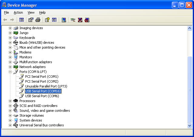
Note that by default, chipKIT boards automatically reset the MCU when the FTDI COM port is first opened by the host computer. This behavior can be disabled (which is how I run) by cutting the trace under JP1 on the Uno32 or JP5 on the Max32, and then installing a removable jumper. If you have cut this trace, you will need to manually reset the board immediately before running avrdude, below, or temporarily install the jumper on the board. If you have not cut the trace, then every time you subsequently connect the terminal emulator to the board, the MCU will be reset. During the 4 seconds following reset, you must not enter any input on the terminal emulator or the bootloader will crash! After 4 seconds with no input from the terminal emulator, the bootloader will automatically transfer control to StickOS and then you can then press <Enter> to get a command prompt.
